Blow molding & Blow molding technology
A information from the field of process engineering blow molding:
Blow molding of hollow plastic parts
Blow molding plastic containers by continuous extrusion
In case of blowmolding, during the first process step the heated extruder of a blowmolding machine obtains plastic grain which is then condensed, freed from gas, plasticized and finally homogenised to become a plastic parison.
Then, the plastic material is fed into the parison head which is flanged to the extruder.
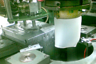
Here, the melted plastic material is formed into a hose. The hose leaves via a die vertically downwards. The hose diameter is adjusted to the article to be blowmoulded by using standardized blow pins and dies which are flanged to the parison head. The parison thickness and the weight of the blowmoulded articles resulting from the parison thickness are predetermined by selecting varying diameter differences from blow pin to die.
In case of strongly contoured blowmolded articles, different stretching directions result in different wall thicknesses within the blowmolded articles. In order to avoid these unwanted effects with regard to article quality, the wall thickness of the parison is changed by modifying the axial position of the conical blow pin towards the die. Blow pin and die are either internally or externally conically designed.
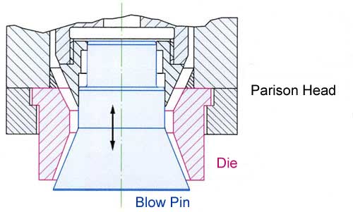
(Figure = externally conical)
The parison gets heavier the more it gets out of the die. The heavier it gets and the longer it stucks in the parison head, the stronger the parison is stretched through its own weight. For this reason, wall thickness control is used to counteract sagging (and thus consequently also parison thickness reduction).
When producing blowmolded articles with strongly elliptical cross section, blow pin or die, normally will also be elliptically profiled in order to allow for the different stretching directions within the blowmold tool. The thinning in the area of great stretching areas is reduced by different parison wall thicknesses on the circumference.
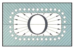
Figure on the left: Cross section (top view) through blowmold including elliptically profiled parison/preform. Arrows = stretching ways during the blow process.
A consistent wall thickness of the blowmolded articles is of decisive importance for the material consumption. An optimum wall thickness ensures even surfaces without ribs. Cooling time can be considerably reduced with a highly constant wall thickness. In case of technically demanding blowmoulded articles, the radial profiling will be modified even during the blowmolding cycle. The profiling is modified by means of a flexible ring which can be precisely deformed via servo positioning cylinders. This process is called PWDS (Partielle WandDickenSteuerung = partial wall thickness control).
In the next step of the blowmolding process, the water-cooled blowmold closes around the extruded preform. Via a separator (knife, hot-wire cutter or parison closing flap) the preform is separated from the plastic parison which is continuously coming out of the die. During the separation process – or shortly after the separation process – the clamping unit with the blowmold tool inside moves in inclined position under the plastic material into the blowing station.
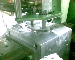
When the blowmold tool reaches the blowing station, a water-cooled blow pin penetrates into the preform within the blowmold tool. The top of the blow pin forms the neck contour of the future plastic article and feeds the inner side of preform with compressed air while the preform is squeezed into the blowmold tool.
The compressed air stretches the preform. The preform then clings to the cooled wall of the blowmold tool. The air on the outer side of the preform escapes via the parting line of the mold and – in addition to this - via vent holes added to the mold. The hot deformable plastic material, which is being pressed against the wall of blowmold tool by means of compressed air then will release a great portion of its thermal energy to the cooled blowmold tool and solidifies. Normally, blowing pressures of 6 to 10 bar are used when blowmoulding polyolefine materials.
Due to the production process, the thermal energy is released via the outer side of the blowmolded article. Since plastic material is a poor heat conductor, the necessary blowing time and – consequently also the cooling time – considerably increases in a square function with progressing article wall. When doubling the article wall thickness, this requires four times the blowing time.
In order to reduce the long cooling times (and thus the lower productivity), of blow-molded articles with great wall thickness the inner side of the article is also cooled by means of purge air, reversible fans, water veils, cyrogenic CO2 or liquid nitrogen.
The following factors influence cooling time and – consequently – an economical blowmolding production:
• Specific thermal capacity of the plastic material to be processed
• Thermal conductivity of the plastic material
• Colour pigments and additives
• Melting temperature
• Article wall thickness
• Regularity of the wall thickness
• Inner cooling CO2 / N2
• Inner cooling with purge air / reversible fans / water veils
• Demoulding temperature
• Post cooling device
The design of the blowmold tool also influences cooling times by using the following concepts:
• Drilled cooling channels
• Counter-milled cooling channels
• Encapsulated cooling tubes
• Distance between the cooling channels and the blowmould tool
• Thermal conductivity of the tool material
In addition, the cooling time of the blowmolding process is influenced by:
• Cooling water consumption
• Cooling water temperature
• Dew point of the surrounding air to which the temperature of the cooling water
needs to be aligned (otherwise the condensate will cause markings on the surface
of the blowmoulded article).
The blowing process is finished on the basis of a preset period of time. In the following period of time the compressed air still in the blowmolded article can escape via the blow pin. Then the blowmould tool opens and the blowmoulded article including scrap remains on the blow pin. As soon as the next preform reaches the required length monitored via photoelectric cell, the clamp unit including blowmould tool returns to the position directly underneath the parison head.
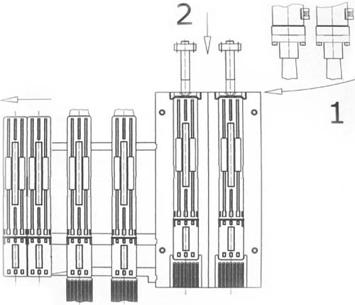
When reaching this position, the blowmold tool again closes around the preform. The blowmold tool is equipped with mask arms which close around blowmolded article, which still hangs on the blow pin, and hold it. Then, the blow pin moves out of the lower position to the top. During this movement, the blowmolded article stays within the mask arms.
As soon as the blow pin reaches the upper position, the blowmold tool returns back into the blowing station (Movement “1”) and at the same time it transports the blowmolded article, held in the mask arms, into the deflashing station which is equipped with guiding rods. When the blowmold tool moves down, at the same time the mask arms push the blowmolded article of the previous cycle, still in the deflashing station, further along the guiding rods out of the blowmolding machine.
The blow pin again penetrate into the blowmold tool (Movement “2”). The next preform is blown. In the deflashing station, the scrap of the preform sticking out of the blowmold tool upwards and downwards is separated by means of a punching device. These segments called scrap are then transported to the grinder. The scrap is grinded there and will be added to the production process as regrind.
Shrinking of the article
The article shrinks during the cooling process within the blowmold tool as well as outside. This means, that the finished article is smaller than the cavity within the blowmold tool.
Criteria for shrinking of blowmolded articles:
• Type of plastic material
• The article temperature at the time of removal from the blowmold tool
• Colour pigments and additives
• Article wall thickness
• The stretching relation of preform and article dimension
Example: a blowmolded article produced out of HDPE with a wall thickness of 1 mm will shrink by approximately 1,7 % with usual cycle times. An article produced out of HDPE with a wall thickness of 5 mm will shrink by approximately 2,5 %. In the beginning, the shrinking process quickly continues, normally will only be finished after 24 to 48 hours after production. For this reason, to ensure quality the time passing between article production and collection of article dimensions data is essential. The same applies to the point of time for a possible article finishing, e. g. drillings requiring exact center distance.
Blowmolded article before and after deflashing
Within the blowmold tool, the scrap area often is equipped with ribs thus increasing the cooling area and giving the scrap a higher stability during punching.
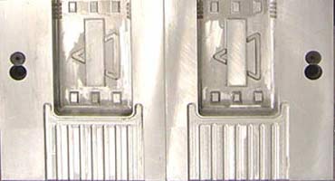
The picture above clearly shows the cutting edges sticking out to the mold parting surface. When processing polyolefines (PE * PP), different to what is shown above, the cavity is sandblasted. The surface structure thus created avoids that the melted plastic material seals the blowmold tool, that air bubbles are imbedded and a complete venting of the cavity fails, that the article surface is not formed correctly.
Necessary clamping forces for the processing of thermoplastic materials are calculated per running cm scrap separating edge when processing:
LDPE 800 - 1000 N/cm
HDPE 1000 - 1200 N/cm
HDPE high molecular 1600 - 1800 N/cm
PP 1500 - 1800 N/cm
PC 1600 - 1900 N/cm
In addition to these separating forces forces of scrap squeezing need to be considered. The force created by the blowing pressure (blowing pressure x projected cavity surface on the parting surface , is not created at the time when the blowmold tool closes and consequently does not need to be added to the number of separating forces. Essential for the clamping forces required is which of these two forces is higher (plus safety margin).
Blowmolding on a single station blowmolding machine Kautex KEB 2-11. Seen from the electrical point of view:
(KEB 2 = Kautex injection blowmolding machine up to 2 l article volume, with continuous extrusion)
Blowmolding with Continuous Extrusion
At the beginning of the blowmolding cycle, the blowmold tool is open in the lower end position, the blow pin is in lower end position, the deflashing device is in basic position. During the mold opening movement, the initiator “Opening Limitation” is actuated. This initiator starts the function “Lifting of Clamping Unit”. When the upper final position is reached, the initiator “Upper final position” is actuated. If the photoelectric cell is switched off, this initiator provides the signal “Mold closing”. If the photoelectric cell is active, the initiator gives the starting signal for the correction of parison length.
As soon as the photoelectric cell registers the extruded parison, the following steps will be executed:
1.) “Mold closing” is started;
2.) “Target/actual comparison” of present and actual period of time between upper final position and the signal of the photoelectric cell is started
If the actual period of time is smaller than the target time, the extruder speed is reduced. If the actual period of time is greater than the target time, the extruder speed is increased.
The blowmold tool closes
1.) around the extruded preform/hose
2.) The mask arms mounted to the blowmold tool close around the blowmolded
article which hangs on the blow pin in lower position
Shortly before the position “Mold Closed” is reached, the initiator “Blow pin return” is actuated, which starts the return of the blow pin cylinder.
At the same time, the initiator “Blowing” is actuated, which gives the start signal for the timer “Cutter foreward”, “Start impulse support air” as well as for “Wall thickness control 1. Programme point”.
The cutter separates the preform.
The blow pin cylinder actuates in the upper final position the initiator, which releases the function „Lowering clamping unit”. The deflashing device needs to be in basic position or needs to be returned to basic position. The clamping unit moves to the lower final position.
The initiator “Lower final position” starts the function “Blow pin injection” and gives the start signal for the timer “Blowing deferred” and “Deflashing device foreward deferred”.
The blow pin lowers into the preform positioned in the blowmold tool. Depending on the length of the period of time selected for “Blowing deferred”, the molding process starts even before the blow pin is moved completely into the blowmold tool. Due to the early exit of compressed air, the hose tulip continues to open more and more. This is to avoid that overturning parison ends are molded into the article. In addition, the flush of compressed air leads to cooling down the material in the neck area, which often has a positive effect to the quality of the article surface of the inner neck surface of the article.
The inflation time is ending. At the same time, the time for “Deflashing foreward” ended and the deflashing device moved foreward already. As soon as the timer “Deflashing device backwards” has finished, the deflashing device returns into basic position. After the inflation time expired, the timer “Venting” starts. The compressed air in the blowmolded article escapes.
With the ending of the venting time, the blowmold tool opens (deflashing device must have actuated end switch “Deflashing Device Backwards”). The blow molded article including scrap keeps on hanging on the blow pin in lower final position. As soon as the blowmold tool actuated the end switch “Opening Limitation”, the blow molding machine is ready for the next cycle.
Competence team Blow molding & Blow molding technology
Three specialists who take care of your task with their common know-how:
Blow molding + Blow molding machines + Blow molding technology:
Your partner for blow molding, blow molding technology and blow molding machines.
Johannes Tack
Managing director of Xeel GmbH Bonn www.Blasformmaschinen.de
10 years of experience with our own blow molding plant as an automotive supplier.
Design of blow molding tools, production optimization, design of extrusion heads.
Purchase and sale and placement of used blow molding machines.
Construction + development, reworking devices, retrofit blow molding machines.
Your contact for construction + development blow molding machines + rework devices, retrofit.
Steffen Frey, mechanical engineer
Managing director of Sagittarius GmbH, 53757 Sankt Augustin www.Sagittariusgmbh.de
Many years of experience in the construction of plastic processing machines, blow molding machines and finishing lines
Call Mr. Frey now +4922414938855
or contact us by e-mail at info@sagittariusgmbh.de.
Plastics technology + production technology in the blow molding and injection molding area + commercial area
Your contact for the field of plastics technology, production technology and commercial contract drafting
Jürgen Moitzheim, CCI of Plastics and Rubber and B. Sc.
Managing Director Moitex, owner-managed by Jürgen Moitzheim, Dachsweg 15, D-53639 Königswinter
Many years of experience in plastics processing in various fields of technology and commercial implementations
Call Mr. Moitzheim now: +49(0)1702451877 or contact us by e-mail at: moitex@t-online.de
Further pages:
Extrusion blow molding: Extrusion as the first process step.
Blow molding with accumulator head / Discontinuous preform feed.