Extrusion blowmolding: Extrusion = first process step
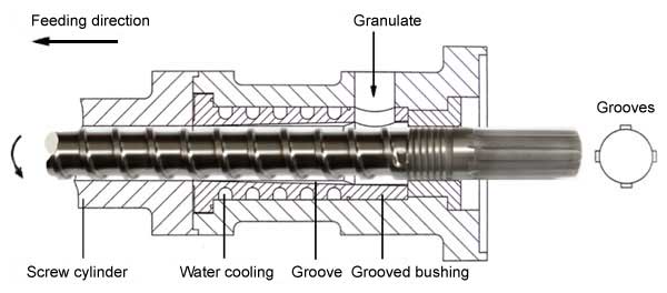
The first process step in extrusion blowmolding is to transport thermoplastic plastic material (as pulver or granulate) to the extruder. By means of its rotary motion, the screw within the extruder takes up the material in the area of the feeding area and condenses the material. During this process, the air around the granulate escapes via the material hopper. This process is also called “gas venting”.
The plastic material is transported further in feeding direction and gets the necessary melting temperature via the heated wall of the screw cylinder and via the frictional heat resulting from the rotary motion.
The frictional heat resulting from the screw rotation during the continuous production many a time can exceed the heat demand for granulate melting. For this reason, extruders often are equipped with fan cooling which leads away the excessive heat.

To increase the feeding capacity and to improve the feeding consistency which is of high importance for extrusion blowmoulding, the feeding area of the extruder has a grooved bushing when processing polyolefines. The bushings which end cone-shaped over a length of mostly 3 times the screw diameter, shall avoid that granulate particles stick on the screw and then rotate on the screw only stationary instead of being transported continuously by the screw flank. Newly developed feeding zone concepts work with grooves with helix groove bushings in greater length relations.
Normally, the feeding area is cooled with water. In order to keep the thermal losses at the connection area between groove bushing and heated screw cylinder as low as possible, the contact areas between the feeding zone and the screw cylinder are reduced to a small circular ring area.
In case of hard materials, like for instance polycarbonate (PC), groove bushings are not used, since otherwise the screw charge and thus the power input of the extruder engine increase too much.
Criteria for extruder feeding capacity:
• Screw diameter
• Screw inclination
• Flight depth of the screw
• Screw speed
• Design of the feeding zone
• Temperature in the feeding zone
• Bulk density of the granulate to be fed
• Temperature of the screw cylinder
• Viscosity of the plastic melt
• Flow resistance of the parison head
Correction of extruder speed
The extruder blowmolding process always should bring exactly the same quantity of plasticized material within a defined period of time. Since influencing factors like bulk density, lot differences und changing temperatures in the area of extruder and parison head (and the differences in the viscosity of the extruded materials resulting out of this) continuously change the feeding capacity, extruder speed corrections measures are applied.
Technically this is realized by comparing the period of time between the signal “Blow mold in upper end position” and the signal “Correct length of preform reached”, which is monitored by a photoelecretric cell. In case the time is too short or is “0”, the extruder speed is automatically reduced. In case, the time is too large, the speed is increased. The target / target values of this blowmould tool waiting time mostly amount to 0,1 to 0,4 seconds. In case of very long articles, this rule may extremely “build up”, which means that a continuous production is no longer possible. In this case, the speed correction needs to be switched off and longer mould dead times are the consequence.
Extrusion blowmolding: Forming of the preform with the parison head
Example: Torpedo head

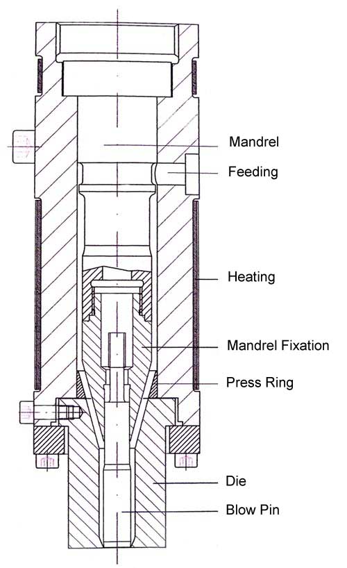
Extrusion blowmolding means feeding of plastic melt coming from the extruder via bored injection holes into the parison head. Here, the plastic melt reaches the radial notch of the mandrel and circulates around it. On the back side of the radial groove the extrudate portions, splitted by the mandrel, encounter again and weld here. Then the plastic melt flows across the center bar of the radial notch downwards. Further down the channel, in the shape of a circular ring, pressure balance takes place, i. e., adjustment of flow speed.
The press ring, pressed against the die by the melt pressure, seals the connection to the radially adjustable die. The flanged head tools (mandrel and die), the diameter and the wall thickness of the extruded preform are adjusted to what is required for the blowmoulding article to be produced. By means of a pull rod and servohydraulic actuator (not shown here) the mandrel is displaced axially during each production cycle. Due to the conical design of the mandrel, the wall of the preform, and consequently also the wall thickness of the article to be produced, changes.
This type of head can only be used for extrusion blowmolding process with continuous extrusion.
Advantages of this parison headtype:
- Relativley favourable production
- Die design allows small centre distance
- Mechanically easy wall thickness control
Disadvantages of parison head type:
Unfavourable material changeover times since sediments and colour pigments gather in the welding area of the radial notch which are washed away only very slowly. Due to uneven temperature distribution, caused by varying melting temperatures, an uneven flow behaviour occurs. To counteract this flow behavior, the die needs to centered or decentered. Due to the fact that temperature conditions change during production or especially during production start-up, many a time the die position needs to be readjusted. If it is not readjusted, the wall thickness of the blowmoulded article is inconsistent. It might happen that scoring and thin points occur in the blowmoulded article in those areas where the extrudate was melt again to the mandrel.
Parison head for production with diffrent Layers:


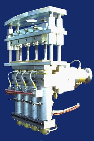
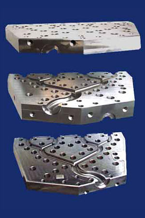
By means of this parison head, at a time simultaneously four preforms are produced. With a single machine cycle, thus 4 articles can be produced. Additionally, this parison head is fed with 2 differently coloured materials via two extruders so that articles are produced consistingly out of two different layers. The distribution plates (de-assembled), shown in the right-hand side figure above, steadily feed the plastic melt delivered by two extruders equally portioned to the four individual parison heads.
Further pages:
Extrusion blow molding with continuous extrusion
Blow molding with accumulator head / Discontinuous preform feed.